Led Strip Schematic Diagram - VLIGHTDECO TRADING (LED): Wiring Diagrams For 12V LED Lighting / Solder the pins to the led strip.. Any one can make it at home as it is very simple and the basic components can be found at any electronic components shop. The final circuit in the simple led circuits tutorial is leds in parallel. 20ma draw from the red leds, 20ma draw from the green and 20ma from the blue. Solder the pins to the led strip. Circuit diagram of leds in parallel.
To make this simple led chaser circuit i have used only a 4017 ic. Connect the led driver to the mains supply. 1) the specified voltage of the leds and components used, and. The picture below shows the relation between led strip ws2812b rgb and arduino uno. You can make 100w dimmer circuit, motor speed controller with this board.
Pin on WS2812 from i.pinimg.com Did not had power supply of 12v 2/3 a , so i had to use the closes i. We'll use white for +12v, then red, green and blue wires for the corresponding led colors. The final circuit in the simple led circuits tutorial is leds in parallel. I decided to do this same project with slightly differences as in some of the updates mentioned in the comments. As you know this post is about hisense led tv schematics diagram/circuit diagram. Here the flashing rgb led will generate the clock pulse for cd4017 ic. Before we talk wiring though, take a look at my article about 12v vs 24v led strip.in the following diagrams i will be talking about 24v led strip only, when using 12v take into account that the maximum lengths mentioned should most likely be kept shorter, the same goes for very cheap led strip! In this instructable you will learn about the basic kinds of strips and how to hook them up to the intel edison with arduino breakout board.
The basic principle behind the 230v led driver circuit is transformer less power supply.
Cut away the waterproof overmolding at one end of the strip. The picture below shows the relation between led strip ws2812b rgb and arduino uno. 3 wire led strobe light wiring diagram at manuals library. You can make 100w dimmer circuit, motor speed controller with this board. Schematic diagram of tester for led tv backlight with complete details of the parts needed. The basic principle behind the 230v led driver circuit is transformer less power supply. Then 4017 ic will blink the leds in sequence as per the signal in the clock pin (14). These lcd schematic diagrams will help you to repair your screen by yourself. Connecting up to the strip is fairly easy, you'll want to solder four wires to the copper tabs. Thus, the best way to power up both arduino and the ws2812b led strip, is by using an external 5v supply that can provide sufficient power. The cathode is marked on the rim of the led body with a flat area shown in the. Circuit diagram of led chaser. On the physical led, the longer lead (or leg) of the led is the anode.
We hope that project's power supply section is clear, moving to project's schematics now. Make sure your power supply can deliver adequate amount of current for led strip. Thus, the best way to power up both arduino and the ws2812b led strip, is by using an external 5v supply that can provide sufficient power. On the physical led, the longer lead (or leg) of the led is the anode. The same type of security protection can be arranged with microcontrollers such as arduino, raspberry pi, pic ics, and many other controllers.
Wiring Diagram Rgb Led from www.bengigroup.com Greetings newbie help for led flasher circuit all about circuits. On the physical led, the longer lead (or leg) of the led is the anode. Insert the 4 pin connector into the ir controller. As you know this post is about hisense led tv schematics diagram/circuit diagram. Components required for leds in parallel We'll use white for +12v, then red, green and blue wires for the corresponding led colors. Also, it's mandatory to add an 0.1uf capacitor to the vcc and gnd of each ws2812b. Schematic of the led brightness control circuit.
The basic principle behind the 230v led driver circuit is transformer less power supply.
Wrg 7511 12 volt led wiring diagram with relay. Schematic diagram of tester for led tv backlight with complete details of the parts needed. The occasion for this project was retrofitting an illuminated wall picture with led backlighting. How to read a laptop schematic diagram? Greetings newbie help for led flasher circuit all about circuits. Cut away the waterproof overmolding at one end of the strip. Schematic of the de led controller. These diagrams will help you to correctly discover where the problem lies. Wiring led strip seems simple but becomes more complex the longer the length becomes. On the physical led, the longer lead (or leg) of the led is the anode. Schematic of the led brightness control circuit. Then 4017 ic will blink the leds in sequence as per the signal in the clock pin (14). The circuit diagram for leds in parallel connection is shown in the following image.
Then 4017 ic will blink the leds in sequence as per the signal in the clock pin (14). In this circuit, we will try to connect three 5mm white leds in parallel and light them up using a 12v supply. Connecting up to the strip is fairly easy, you'll want to solder four wires to the copper tabs. Circuit diagram of led chaser. They are easy to cut at the boundary of each section, theres a little cut mark area and some copper tabs you can solder to.
Controlling LED Strip Light ON/OFF and Brightness with any Remote Control | Homemade Circuit ... from homemade-circuits.com The circuit diagram for leds in parallel connection is shown in the following image. Timing diagram for a single bit of value 0 or 1. Then, set the flexible led strip and receiver on a flat surface and bend the pins down so that they touch the solder pads on the. 2) the configuration of the leds on the led strip. We'll use white for +12v, then red, green and blue wires for the corresponding led colors. The cathode is marked on the rim of the led body with a flat area shown in the. It is a very interesting circuit of blinking/dancing and flashing led string / strip. The final circuit in the simple led circuits tutorial is leds in parallel.
They are easy to cut at the boundary of each section, theres a little cut mark area and some copper tabs you can solder to.
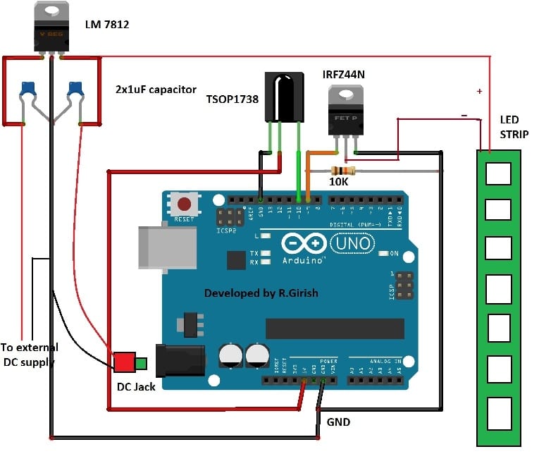
Schematic of the de led controller. The proposed circuit is designed for 12v led strips, you can change voltage regulator depending on led strip specification. In this circuit, we will try to connect three 5mm white leds in parallel and light them up using a 12v supply. Wrg 7511 12 volt led wiring diagram with relay. Components required for leds in parallel We hope that project's power supply section is clear, moving to project's schematics now. You can make 100w dimmer circuit, motor speed controller with this board. 88light flexible led strip light to driver and adapter wiring. So let's know what models are included here. Any one can make it at home as it is very simple and the basic components can be found at any electronic components shop. The cathode is marked on the rim of the led body with a flat area shown in the. The voltage regulator powers arduino and led strip. We have 12v and 5v supply from the circuit board in hand.